New Diaphragm Layout Plot
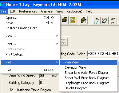
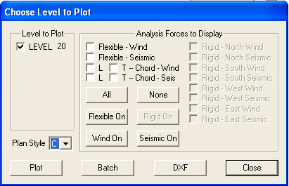
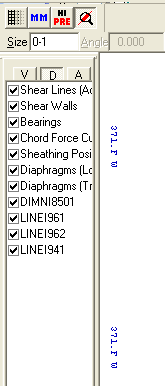
The Diaphragm Layout Plot is a variation of the previously existing Plan View Plot with a default concentration on the geometry of the diaphragms on the subject level. To produce this plot, select the Plan View Plot through the File | Plot | Plan View menu (or the associated toolbar button), and set the Plan Style to "C"
By default, the following entities are visible on this new plot: a representation of the level’s diaphragms in the longitudinal orientation; a representation of the level’s diaphragms in the transverse orientation; diaphragm dimension indications; diaphragm labels; the standard plan view plot legend; and the standard KeyLat plot block.
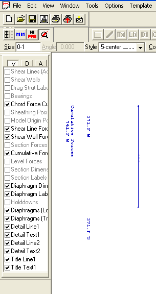
Since the diaphragms from both orientations are displayed simultaneously by default, the user needs to control the visibility of one orientation or the other to properly view the diaphragms in the orientation of interest. In the visibility checklist, check off whichever orientation is not desired, and the orientation of interest remains. Each section of each diaphragm is hatched in the same direction to indicate membership in the diaphragm. Adjacent diaphragms are hatched in the opposite direction.
By default, the following entities are available for view but invisible on this new plot: both active and inactive shear lines; shear walls; drag strut labels; bearings; sheathing position; model origin position; section dimensions and labels; and holddown positions. Each of these entities can be made visible using the visibility checklist if desired.
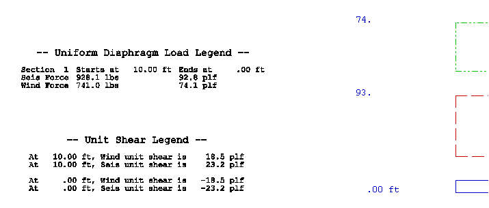
New Legends on Diaphragm Free Body Plot Containing Unit Shear and Diaphragm Loading Information
The Diaphragm Free Body Plot was not as useful as it could have been, because it presented no information concerning forces at key locations or loading on pieces of the diaphragm. The addition of two legends to the plot addresses this shortcoming.
The Unit Shear Legend is a supplement to the Unit Shear Curve on the plot, and appears directly to the left of it. It lists the wind and seismic unit shears at each section boundary within the plotted diaphragm.
The Uniform Diaphragm Load Legend amplifies the diaphragm force diagrams on the plot, and appears directly to the left of it. It describes the width of each section of the plotted diaphragm, and lists the wind and seismic forces and unit forces on each section.
Modification of Calculation of Shear Wall Unit Force To Use Full-Height Sheathing Length Rather Than Physical Wall Length
In addition to the geometric length of a shear wall, KeyLat calculates the total length of the portions of the shear wall that are sheathed from top to bottom – the full-height length. That length value is used to calculate the unit forces on the wall. It is reported for each shear wall (along with the geometric length) in the Wind Report, the Seismic Report, the Rigid Wall Report, and the Rigid Master Report. The total full-height wall length on a shear line is displayed on the Shear Line Detail dialog. The full-height wall length of a wall is shown on the Shear Wall Data Display dialog.
ASCE7-05 All Heights Procedure For Wind
The Building Code – Wind combo box on the main KeyLat view now contains “ASCE-7 05 ALL HGTS” as a supported choice for wind force generation. As with the other ASCE7 choices for wind, KeyLat relies upon KeyWind for the generation of wind forces on each tributary area for ASCE7 05.
The Wind settings portion of the main view displays the relevant ASCE-7 05 settings used in the calculation of wind forces by KeyWind.
In all instances of output that reference the wind building code, “ASCE-7 05” and its sections are referenced where appropriate.

NOTE – ASCE-7 05 must be selected within KeyWind when processing the subject structure so that the settings and results are available to KeyLat when chosen.
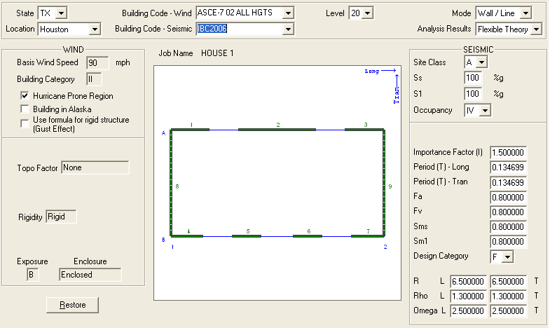
ASCE7-05 Seismic Along With Alias Design Codes IBC2006 and CBC 2007
The Building Code – Seismic combo box on the main KeyLat view now contains “ASCE-7 05”, “IBC2006”, and “CBC2007” as supported choices for seismic force generation. A choice of IBC2006 or CBC2007 instructs KeyLat to use ASCE-7 05 for seismic force generation, but to apply the named design code and reference it in all output.
The Seismic settings portion of the main view displays the following settings and factors: Site Class; factors Ss and S1; Occupancy category; Seismic Importance factor; structure period in each orientation; factors Fa and Fv; factors Sms and Sm1; Design Category; factor R in each orientation; redundancy factor Rho in each orientation; and factor Omega-o in each orientation.
KeyLat uses the ASCE-7 05 equations to calculate base shear, including its floor and ceiling limits (equations 12.8-1, 12.8-2, 12.8-3, and 12.8-5). It “calculates” the redundancy factor Rho to be 1.0; if another value is required because of certain structural conditions, the user needs to enter the desired value on KeyLat’s main view in the seismic settings area. All ASCE-7 05 equations and tables used by KeyLat in its calculations and decision-making are referenced in the output as appropriate, particularly in the Summary Report.
KeyLat calculates the wind and seismic aspect ratio material adjustment factors for each shear wall based on its geometry (that is, the aspect ratio of the portions to be sheathed from top to bottom). These adjustment factors are applied to sheathing material capacity during the material selection process. In previous building code implementations, the sheathing chosen for a shear wall was governed by the larger of the wind and seismic forces. For ASCE-7 05/IBC2006, KeyLat chooses the wall sheathing based on its capacity separately adjusted by the wind and seismic aspect ratio adjustment factors (in conjunction with the specific gravity adjustment factor and the perforation adjustment factor).
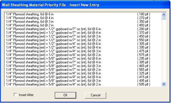
Wall Sheathing Material Tables per ASCE7-05, Including Alternate Capacities if Specified
The master wall sheathing material file, VMATW.DTF, was repopulated with entries conforming to Tables 2306.4.1(wood structural panels), 2306.4.3 (particleboard), 2306.4.5 (gypboard) in IBC2006. The previous contents, dating back to UBC97, were entirely replaced by the new tables. Some of the entries in Table 2306.4.1 specify alternate capacity based on wall framing spacing or sheathing orientation. These alternate capacities are applied appropriately according to user settings at the job level or on a per-wall basis as discussed below.
Since any Wall Priority Files (WPF, from which material selections are actually made by
KeyLat) constructed before now contain material entries from the previous master file
(circa UBC97), KeyLat attempts to update their contents when they are opened for use in
material selection or by the user in the editor (Edit/Material Priority Files/Wall
Priority Files) with analogous entries from the new master file. Some entries are readily
updated, but others cannot be because of changes in terminology. If any entry in a WPF
cannot be updated to the new version, a message is presented to the user warning them of
the situation, and encouraging them to open the WPF in the editor for examination and
potential additions. Failure to heed the warning may result in unsatisfactory design
results, since the WPF(s) used in the design may not contain the materials expected.
To support the application of alternate material capacities as described above, two new controls have been added to the job preferences (Preferences/Job) and to the shear wall settings (Preferences/Shear Wall). The first allows the user to specify the framing spacing for shear walls as inches on center. Provided spacings are 8, 12, 16, 19.2, and 24 inches on center. Additionally, any value between 4 inches and 36 inches on center may be entered. The second provides the means to specify the orientation of shear wall sheathing, either vertical or horizontal.
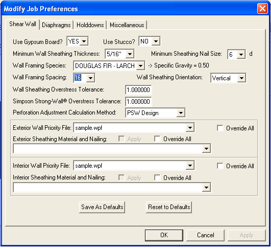
Table 2306.4.1 footnote d denotes and explains the applicability of and conditions for the
use of alternate material capacity. For certain sheathing choices of 3/8” and
7/16” thickness, the higher capacity specified for the 15/32” thickness may be
used when wall framing is spaced at 16” on center or less, OR if the sheathing is
oriented horizontally. KeyLat applies the user’s choices for these two attributes to
use the higher capacity if appropriate.
Support For Choice of Wood Sheathing On One Side of Wall and Gypboard On The Other Side
It is, of course, reasonable
to want to sheath exterior shear walls with structural wood sheathing on the exterior
surface, and gypboard on the interior surface. That practice is now supported by KeyLat.
Most entries in the wall sheathing master file (and therefore updated Wall Priority Files)
pertaining to structural wood sheathing have a duplicate entry that also contains gypboard
use. For example, the sheathing entry
5/16” Structural I
has a duplicate entry available
5/16” Structural I (ext) + ˝” gypboard w/7” oc (int)
Interpret the duplicate entry as follows: 5/16” Structural I sheathing on the
exterior surface, and ˝” gypboard fastened at 7” on center on the interior
surface.
Wherever the option to sheath walls in this fashion is offered, both ˝” and
5/8” gypboard is available, as are fastening at both 4” and 7” on center.
The capacity associated with such an entry is comprised of the appropriate Table 2306.4.1
(structural wood sheathing) capacity plus the appropriate Table 2306.4.5 (gypboard)
capacity. Application of the specific gravity adjustment factor and the aspect ratio
adjustment factor pertains only to the wood sheathing portion of the combined capacity,
and not to the gypboard capacity, as specified in the design code. Additionally, entries
including the use of gypboard will not be selected by KeyLat for use in seismic
application, as specified in the design code; of course, walls can be constructed in that
fashion, but KeyLat does not design them that way since the gypboard capacity cannot be
included in the design selection.
The mechanism for taking advantage of this feature already exists in KeyLat. At both the
job preferences level (Preferences/Job) and the shear wall level (Preferences/Shear Wall),
a Wall Priority File can be specified for use on exterior walls, and the same or a
different WPF can be selected for use on interior walls. Exterior wall WPFs should contain
entries specifying structural wood sheathing only and entries specifying the gypboard
addition. Interior wall WPFs can also contain both types of entry, though probably should
not.
The automated WPF update attempt described earlier will never insert entries containing
gypboard destined for the interior surface of a shear wall. User’s wishing to take
advantage of this new feature must manually add wood sheathing + gypboard entries to their
WPFs using the WPF editor (Edit/Material Priority Files/Wall Priority Files). It is
advised that entries containing gypboard on one surface appear before the
wood-sheathing-only entries so that KeyLat makes the proper choices in both wind and
seismic applications.
Output of Wall Sheathing Specific Gravity Capacity Adjustment And The Wind or Seismic Aspect Ration Adjustment Factor To The Wind And Seismic Reports
![]()
In both the Wind and Seismic
reports, KeyLat now outputs, as part of the shear wall analysis and design detail, the
adjustment applied to sheathing capacity based on the specific gravity of the framing
material species (labeled as “Framing specific gravity adjust factor”). It also
outputs the aspect ratio capacity adjustment factor (labeled as “Source adjust
factor”). Both of these values appear immediately before the wall sheathing suggested
for each shear wall.
The presence of these factors, in conjunction with the perforation adjustment factor
already provided for each shear wall, allows the user to verify the effective capacity
used for the specified wall sheathing material.
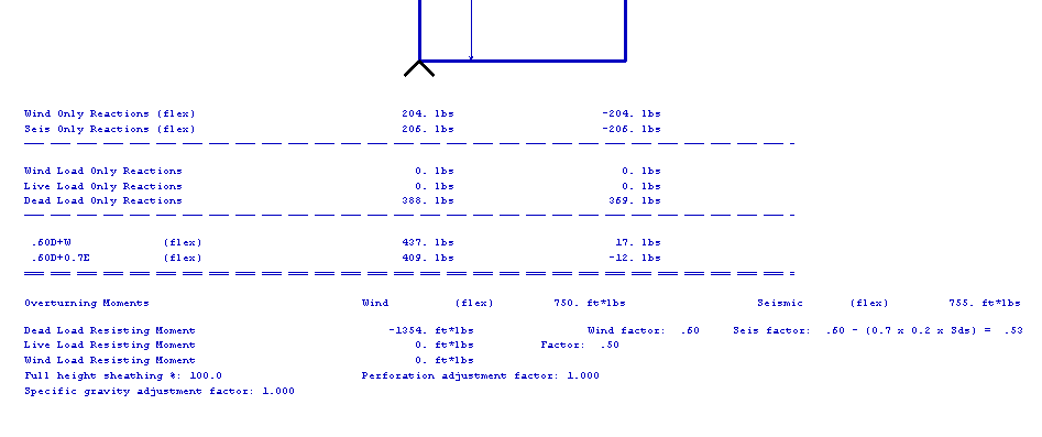
More Values On Shear Wall Free Body Plot
Added the full-height sheathing percentage, the perforation adjustment factor, the framing specific gravity adjustment factor, and the aspect ratio adjustment factor (if applicable based on building code) of the shear wall to the Shear Wall Free Body Plot. These adjustment factors are listed at the very bottom of the plot.