Output Truss Files Directly from KeyBuild!
New features in the KeyBuild program allow you to output truss files directly from KeyBuild to KeyTruss Wood, and soon to KeyTruss Steel! Until now you've only been able to output truss files from the KeyBuild Structure program. The Edit Trusses and Hanger Selection features introduced in this version of KeyBuild are the first of a series of new Design functions being rolled out during 2009 built into the KeyBuild program to replace the KeyBuild Structure program. KeyBuild Structure will still be available for running jobs as we transition to these new Design features.
To output truss files from KeyBuild you need to model your job differently than for output from Structure, you will need to create an accurate three dimensional model. Please read these notes if you are going to use this feature!!!
Designing for Truss Output from KeyBuild
There are a few major differences with how truss information is generated in KeyBuild in comparison to Structure.
1. Accurate 3D Model
The new Design functions in KeyBuild look at the true 3D geometry of your job model for member to member connections. Levels are disregarded so if a member from one level connects to a member of another level, they will be identified as connecting. KeyBuild Structure looked at members on a level by level basis and used a projection method.
2. Bears on Earth Flags
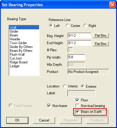
For proper load path development it is up to you to identify the bearings (walls and posts) that are at the bottom of the load path for your job model. It is now possible to get insufficient bearing warnings for walls and posts. A new 'bears on earth' flag is available in the Set Bearing Properties dialog box for Walls, Flush Walls, and Posts, and needs to be set those bearings at the bottom of the load path. Read the "Bears on Earth Flags and Toggle" section below for more information.
3. Truss File Output Destination
Truss files are now always output to your job folder. In the Structure program there is a Truss File Output path that determines where your truss files are saved. From KeyBuild your truss files will be output to the job folder, one folder deeper than where your .LAY and .L## files are saved. The only exception is if your job name matches the name of the folder the job is saved in, and in that case your truss files will be saved in the job folder with your .LAY and .L## files.
4. Edit Trusses for the entire job
The Edit Trusses command allows you to label, edit, and output truss files for your entire job. In the Structure program truss file labeling, editing, and output is done level by level. While in Edit Trusses mode in KeyBuild the Set Levels command is available so you can make level active, visible, invisible.
Design Toolbar
Edit Trusses command
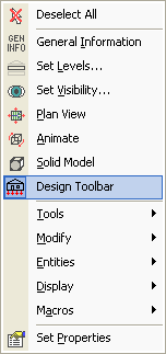
The Design Toolbar is located to the right of the model when the it is turned on. To turn on this toolbar, right-click on the tool bar area and select Design Toolbar. The toolbar can also be turned on by right clicking on the model.
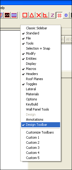
You should now be able to see the Design Toolbar to the right of your model in KeyBuild.

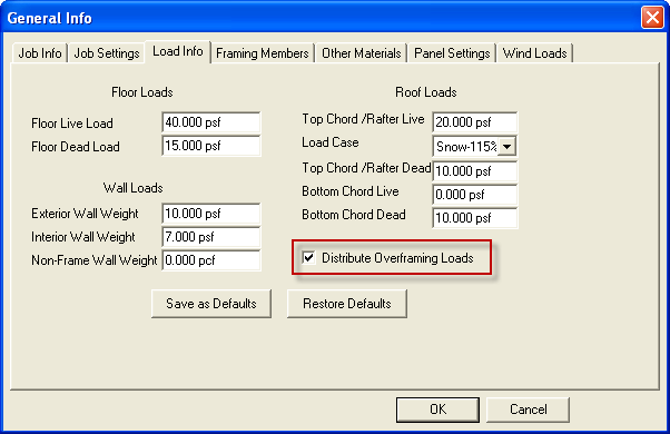
A new preset has been added to the General Info dialog box. Under the Load Info tab a new option has been added to 'Distribute Overframing Loads' onto the common trusses in you structure. When checked standard loads will be distributed to your overframing trusses, and the reactions from overframing trusses will be applied as point loads to the top chords of the supporting trusses below. When unchecked, overframing trusses will be ignored during the distribution of standard loads and overframing trusses will not transfer any loads to supporting trusses below. The supporting trusses below will be loaded as though no overframing exists.
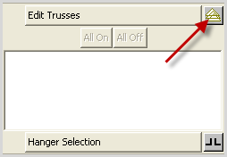
What has happened with this new version of KeyBuild is the truss loading functionality has been moved from the Structure program and merged in as part of the modeling portion of KeyBuild. To use this, once you have defined your roof planes, framing areas, hip ends, etc click on the button located to the right of the Edit Trusses button in the design toolbar.
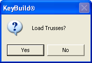
You will then be prompted to Load Trusses. When clicking Yes KeyBuild will distribute standard, additional, and replacement loads directly onto trusses based on your standard loading settings and the geometry of the trusses.
Note: Clicking 'Yes' at this prompt implements the sending of loads from KeyBuild to KeyTruss to load all trusses, overriding truss loading settings in KeyTruss. KeyTruss has preset selections that will override any loading sent from KeyBuild if desired. An implication of clicking 'No' at this point is that no overframing loads will be applied trusses when designed. KeyBuild loads trusses based on your job model as input, and adjust loading for any changes in spacing, moved or deleted trusses, etc.
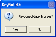
Next you will be prompted to Re-consolidate trusses. This functionality will group all trusses similar in loading and geometry together resulting in a quantity for similar trusses. If you've run Edit Trusses with the current job previously clicking Yes will clear any manual consolidate you've done before, while clicking No will save previous consolidation.
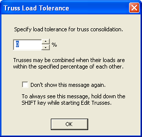
You will them be prompted to provide a load tolerance. Edit Trusses will consolidate like trusses together based on truss profile, bearing locations, and loading if you have clicked Yes to Load Trusses. Enter in a percent difference in total load that can be tolerated for grouping. So for example if you enter 20%, all trusses with the same profiles and bearings, and total load applied is within 20% of each other, they will be consolidated (labeled) together. If you want to use the same tolerance every time they can also opt to not see this dialog by placing a check mark in the 'Don't show this message again' check box.
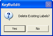
If you have already designed trusses and previously assigned labels you can opt to rename the trusses based on your new changes or you can keep the same labels. Clicking 'Yes' will delete all labels and rename all trusses.
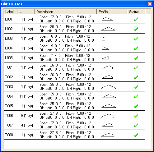
Edit Trusses Dialog Box
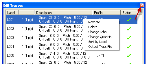
The Edit Truss Dialog Box allows you to apply various edits to trusses. Below is a preview of the Edit Truss Dialog Box.
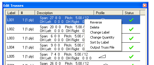
When this dialog box is opened you can right click on any of the truss consolidation groups in the list and perform a variety of functions including: Reverse, Delete, Change Label, Change Quantity, Sort by Label, Output Truss File. If you hold down the Control Key (CTRL) and then select with the mouse you can select multiple.
Reverse
The Reverse function allows you to reverse the geometrical orientation of the selected truss. Reversed profiles will be sent to KeyTruss reversed. This is most commonly used with mono truss to make their orientation consistent, sloping down to the left or right, which helps optimize the changing of the jig setup for truss assembly tables.
Delete
The Delete function allows you to delete truss consolidation groups from the Edit Trusses list. Note this will not delete any trusses from the layout.
Change Label
The Change Label function allows you to change labels that are assigned to each truss consolidate group.
Change Quantity
The Change Quantity function allows you to change the quantity of trusses for each truss consolidation group.
Sort by Label
The Sort by Label function allows you to sort trusses in the Edit Trusses list by label after changes have been made.
Output Truss File
The Output Truss File function allows you to output individual truss files to be designed by KeyTruss. This option can also be performed for multiple trusses if multiple trusses are selected before 'Output Truss File' is activated.
Combine Trusses
The Combine Trusses function allows you to combine two truss profiles into one. To do this, hold down the Control Key (CTRL) and select all trusses you would like to combine. Once you have selected all of the desired trusses right click the truss that has the label you would like to label the combined trusses. See below:

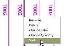
Split Trusses
The Split Truss command is available when you right-mouse click on a truss in the layout, and allows you to break out an individual truss from a truss consolidate group. In this example for a run of consolidated T002 trusses a single truss can be broken out, and given its own label.
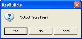
Once all desired modification have been made in Edit Trusses click on the close button at the top right of the Edit Trusses dialog box:
You will be given the option to output all truss files, or cancel and return to Edit Trusses. Clicking Yes will export all truss files for design in KeyTruss. Note that truss files (.ITR and .ITF) are exported into the job folder and no longer are placed into a designated 'truss files path.'
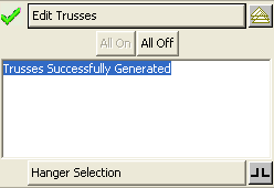
Once this step has been completed the following message will appear in the Design Toolbar:
Bears on Earth Flags and Toggles
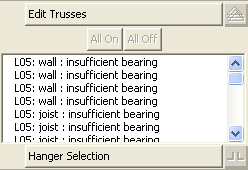
It is possible to not get the 'Trusses Successfully Generated' message in the Design Toolbar after trying to generate trusses. If bearings at the end of a load path are not flagged as 'bears on earth' in their bearing properties, all items that do not have sufficient bearing will report having bearing errors.
In order to prevent this from occurring activate the 'bears on earth' flag for all Wall, Flush Wall, and Post bearings that are at the bottom of the load path in the Set Bearing Properties dialog box:
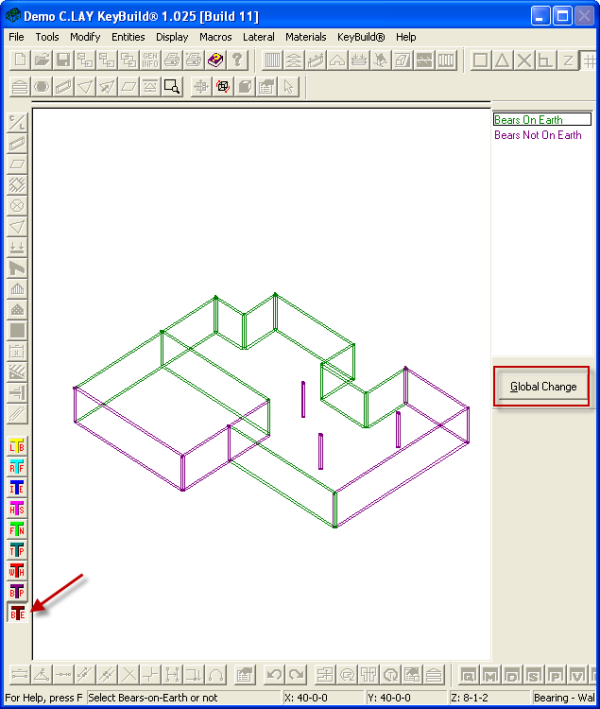
This can also be done using the Bears on Earth toggle. This toggle is located in the Toggles toolbar and the Macros | Toggles pull-down menu, and is denoted with a BE as shown below. Selected either Bears on Earth or Bears Not On Earth on the right of the model area and then click directly on all walls to toggle their properties. Note: All walls can be changed at once if the Global Change button is clicked on.
Note: Load propagation is dependent on these settings to transfer loads from the roof and floors throughout the structure, and if not set properly will cause bearing errors preventing you from continuing to Edit Trusses and Hanger Selection.
Designing Trusses in KeyTruss Wood
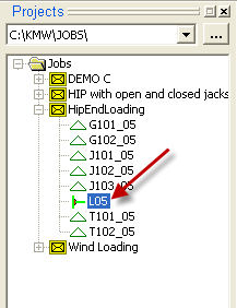
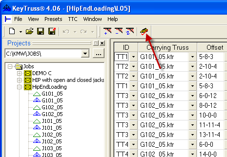
The Truss-to-Truss connection file (.LDG) is exported into the job file as well. In order to transfer all loads from one truss to another and to properly provide loading info for truss design and hanger sizing, the .LDG file must be run in KeyTruss if you have not generated Loads in KeyBuild. To do this, simply double click on L## file signifying a Truss-to-Truss connection.
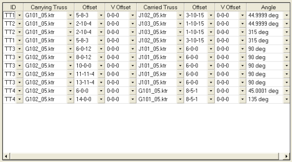
After double clicking on the L## file, a truss connection table will be created detailing all connections.
While on this screen batch designing the trusses will transfer all loads. To do this click on the batch Analyze button.
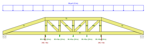
Loads can be verified easily in the loading in the Applied Loads View.
Design Toolbar - Hanger Selection
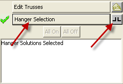
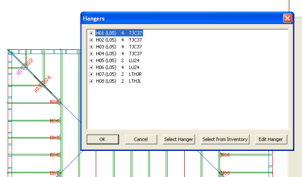
Truss-to-Truss Hanger Selection! Hanger Selection can be handled in KeyBuild as well. To select hangers using the design toolbar click on the 'Hanger Selection' button and then click on the hanger icon next to it.
After clicking on the hanger icon the Hangers dialog box will open detailing all automatically selected hangers. At this point you have the option of selecting alternative hangers or selecting hangers from your KeyMan Inventory. Additionally, you can use the Edit hangers options to customize the hanger options.
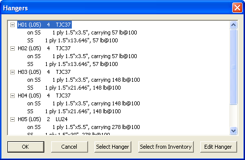
Hanger details can also be expanded to show connection details.
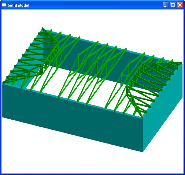
Solid Model View
Once all trusses have been designed in KeyTruss, the next time the model is opened in KeyBuild all truss profiles will be displayed in Solid Model View including all webs and plates.
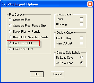
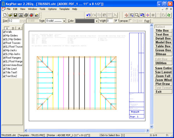
Roof Truss Plot
Roof truss layouts can be plotted while in KeyBuild by clicking on Plot Layout in the file menu. The Set Plot Layout Options window will open and several plot options can be chosen including Roof Truss Plot.